
This article provides considerations and recommendations to the user on luminescence applications and measurements with the Spark® multimode reader. In addition, it also provides quick response steps on how to avoid and prevent a ‘lid check’ error and other damage to the instrument, mainly caused by wrong plate selection.
- Plate definition:
- Ensure to select the correct plate definition file in the software to achieve optimal performance and to prevent potential instrument damage.
- Due to measurement requirements and the design of the Spark, the luminescence measurement head is the component that is spatially located closest to the well plate within the measurement chamber. There is only a minimal clearance between these two components, which is required to minimize crosstalk between the individual wells.
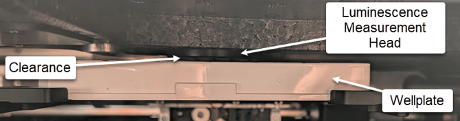 If a wrong plate definition is selected, the plate might crash against the measurement head during operation. This can damage the plate transport or, more likely, damage the luminescence measurement head. It is also possible that the aperture wheel, which is located on this measurement head, is contaminated with sample fluid. This contamination can impair the instrument’s function and may lead to repairs.
 - Adhere to the recommended filling volumes:
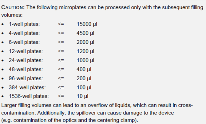
- Plate type:
- Check the article on the Knowledge Portal: Selecting the right plate for a measurement
- White plates are superior for luminescence measurements. The white plate material reflects light emitted by the sample and therefore increases the light output.
- White plates with a transparent bottom may be used if luminescence applications are, for example, combined with absorbance measurements, or if samples are to be visually checked under a microscope. The transparent bottom increases crosstalk (quenching the signal after measurement may be an option). White adhesive tape can be used to cover the plate bottom and reduce crosstalk, but it may still be significant.
- Don’t use transparent plates or plates with lids as this results in crosstalk between wells.
- For AlphaScreen® measurements, we recommend solid white or light grey plates.
- Store white microplates in a dark environment and do not expose them to daylight right before measurement. White plates absorb light and the resulting auto-phosphorescence can result in an inconsistent measurement background.
- Lid check error:
- Basic principle:
- Before every luminescence measurement, the Spark performs a pre-measurement to avoid that external signals interfere with the measurement. In this pre-measurement, the plate is moved to the right back corner of the measurement chamber. The Spark then checks if there are any other signals within the measurement chamber. If external signals exceed a certain threshold, the instrument elicits a "lid check" error and cancels the measurement.
- Important considerations when the instrument detects too many signals in the pre-measurement / quick response steps when a lid check error is detected:
- Check the plate type (as described in point 2 above).
- The Spark must not be positioned in direct vicinity to a strong light source, such as a bright window or a strong ceiling lamp. It must not be exposed to direct sunlight, especially not from the back (fan-openings). If the occurrence of lid check error correlates with the time of day, a connection to sunlight exposure is likely.
- Avoid (fluorescent) liquid spills on the plate carrier, the detector, the aperture wheel and in general in the measurement chamber. Liquid spills can be caused by wrong plate definition files or wrong filling volumes.
- The signals emitted by the samples are too high. The detector is very sensitive, thus the instrument might detect signals from the samples already in the pre-measurement. If this is the case, try the following:
- During the pre-measurement, the plate is moved to the upper right corner of the measurement chamber. As a result, plate columns 1 and 2 are spatially located closest to the signal detector during the check. To avoid that high signals are interfering, it can be tried to reposition the samples with the highest expected signals to the opposite side of the well plate (right-hand side).
- Try diluting the samples.
- Black opaque well plates can be used to reduce signal intensity.
- If the Spark is configured with a Lid Lifter: Use an opaque lid for measurements/samples where very high signals are expected. Then, the high signals do not interfere with the pre-measurement procedure.
- Basic principle:
For further help, please refer to our Tecan Helpdesk.
Selecting the right plate for a measurement: Selecting the right plate for a measurement
Link to Tecan Product Page:
401821-023